An Inexpensive APRS Weather Station
How To Build One
There are two kits you need to get for this weather station. The first is the
outdoor sensor. It costs about $80 and can be bought online from the AAG.
http://www.aag.com.mx
This kit provides the sensor unit (some assembly required) and an interface
that allows you to hook it up to your PC. They are slighly misguided in
thinking a PC is a good weather monitoring platform :-), but we can forgive
them this error because they provide us with a nice sensor package. In
addition to the wind/temperature unit, they also sell a rain guage, also
supported by this project.
The second part you need is the display unit. The kit is available from TAPR
(http://www.tapr.org). If you are truely
impatient or have lots of spare parts around, you can of course just build the
station based on the schematic and instruction manuals below. Links for the
datasheets on big stuff (like the micro and display) are available on the
links page.
Schematic. (pdf)
This is the board schematic. This circuitry will support both a standard
"build-and-go" weather station and can also be used as a general
purpose 1-Wire development station too, all the necessary hardware for the
P&E debug support is included.
Assembly manual (pdf).
This is the assembly document. It is written for the TAPR board, but if you
are the type that likes to roll your own, this is still handy as not only a
construction reference, but also as a checkout guide. This manual takes you
from counting components up through a powered up board with a verified LCD
and verified 1-Wire bus. This manual is intended to be useful during the
construction phase, then pretty much useless unless you break something.
This is the manual that ships with the kit from TAPR.
Operations manual (pdf).
This manual takes over where the assembly manual leaves off. It starts with
the sensor calibration process and shows you how to operate the unit including
all the display features as well as interface features. Features are
being continually added to this project, so this manual will be continuously
updated. As you download new software, you may want to get the latest
version of this manual to go along with it.
(New for releases 1.12.5 and greater)
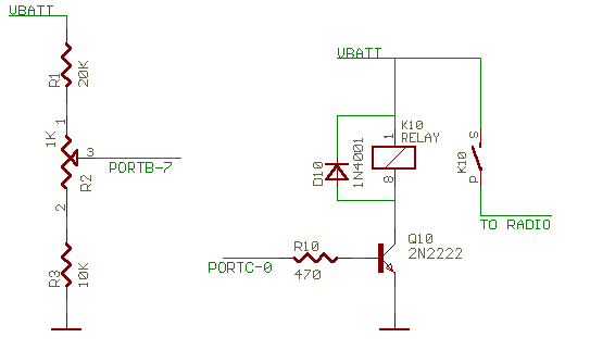
In an effort to better support solar powered applications, release 1.12.5 and
beyond support the ability to digitize the battery voltage for display and
transmission as well as control a radio. Suggested circuits for these two
OPTIONAL circuits are shown below. If you do not want to digitze your
battery voltage and want a simple 00.0V on the display for battery voltage,
ground port B bit 7 (J6 pin 1).
WARNING! Adding this circuit
does interfere with the P&E toolsets ability to boot up correctly. If you
do plan on needing to use that toolset, provide a way to be able to easily
remove R10. The issue is that in order to boot up in the correct debug mode,
Port C bit 0 must be high on the rising edge of reset. There is a 10K pullup
resistor on the main board, but this circuit pulls down harder. This circuit
does not interfere with the Mon08 downloader.

| PARTS LIST |
|---|
| Item # | Part Description | Ref Des. | Quan |
|---|
| 1 | Xtal Osc, 32.000MHz | U1 | 1 |
| 2 | Xtal Osc, 9.8302MHz | U2 | 1 |
| 3 | IC,Motorola MC68HC908GP32 | U3 | 1 |
| 4 | IC, Maxim MAX232CPE | U4 | 1 |
| 5 | IC, LM7805 linear regulator | U5 | 1 |
| 6 | LCD, 2x20 with backlight | DS1 | 1 |
| 7 | LED, Red | DS2 | 1 |
| 8 | Ferrite, Bead | L1-L7 | 7 |
| 9 | Resistor, 2.2K | R1 | 1 |
| 10 | Resistor, 10K | R2-R10 | 9 |
| 11 | Resistor, 1.5K | R11 | 1 |
| 12 | Resistor, 470 | R12 | 1 |
| 13 | Potentiometer, 10K | VR1 | 1 |
| 14 | Cap, 10uF 16V Electrolytic | C1,C2 | 2 |
| 15 | Cap, 0.1uf 50V Ceramic | C3-C7 | 5 |
| 16 | Cap, 1uf 16V Electrolytic | C8-C12 | 5 |
| 17 | Diode, 1N5817 Schotky | D1 | 1 |
| 18 | Diode, 1N4148 | D2,D3 | 2 |
| 19 | Header, 3-terminal | OJ1,OJ2 | 2 |
| 20 | Switch, momentary, N.O. | S1-S4 | 4 |
| 21 | Switch, momentary, N.C. | S5 | 1 |
| 22 | Connector, barrel | J1 | 1 |
| 23 | Connector, RJ11 | J2 | 1 |
| 23 | Connector, DB9 female | J3,J4 | 2 |
| 24 | Connector, DB9 male | J5 | 1 |
| 25 | Header, 14-terminal | J6 | 1 |
| 26 | Heatsink, TO-220 | U5 | 1 |
| 27 | Case | N/A | 1 |
| 28 | Wall-Wart (7V or more) | N/A | 1 |
This page was last updated March 26, 2006.

